Heat Wheel Reliability
There has been much attention paid to all facets of heat wheel performance. An area of concern rarely addressed is reliability. A question was posed, “How long should a heat wheel last?” Rather than try to determine a definitive life span perhaps another question could be posed. “What are the causes of heat wheel failures?” This paper will take an in-depth look at the components of a heat wheel and how each in turn affects
reliability. A heat wheel is nothing more than a disk mounted on bearings in a framework rotating between two opposing airstreams.
Components:
Media, Seals, Hub and Bearings, Shaft, Spokes, Motor, Belts, Rims
Segmented rotor or non-segmented rotor:
A design that utilizes a non-segmented rotor by definition requires that the media or heat transfer substrate bear the physical load of rotation and the lateral stress of the opposing airstreams.
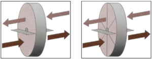 In Figure 1. Structural loads are transferred through the media to the hub. In Figure 2. Structural loads are transferred by the spokes to the hub. The media is not used as a structural component.
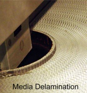
Non-Segmented Wheel
The most common failure of a non-segmented wheel is delamination failure at the hub. All of the stress is transferred to the hub through the media. The weak link is the glue that binds the corrugated media at the hub. The surface area for the adhesion is the smallest near the hub and this is also where the stress is largest. It’s clear that this type of failure is common in this design.
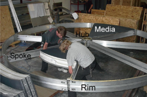
Thermotech Enterprises TF-Series Thermowheel
Segmented Wheels: All segmented wheels use the same basic components to hold the media in place. These components are the hub, spokes, and rims. The goal is that media is secured and cannot move. Each component must be designed to handle the loads and stress involved. The media is easily abraded by any movement inside the rotor. Although these movements of the media may be very small, eventually the media will become loose and cause a catastrophic failure. One of the most critical components is the spoke. Any deflection of the spoke will allow the media to move and cause abrasion of the media.
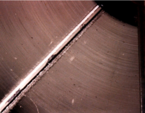
Wheel Damaged by Spoke Deflection
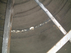
Wheel Damaged by Spoke Deflection
The two wheels to the right both failed due to abrasion of the media caused by spoke deflection. The maintenance staff had to cause the wheel to stop rotating. Spoke deflection should not exceed +/- 1/32” when measured at the outer radius. There is another advantage to limiting spoke deflection. The less deflection the closer to the rotor the seals can be set, reducing bypass and increasing performance. There is also no metal fatigue in a spoke designed to limit deflection.
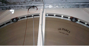
Wheel with Casters to Limit Deflection
There have been some interesting solutions to wheel deflection issues. This manufacturer employed a series of casters to limit the rotor deflection of this wheel. Although the outcome of this design did limit the rotor deflection one can only assume that the casters themselves will become a future maintenance issue.
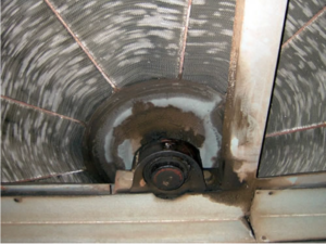
Wheel with Deformed Media Due to Lack of Glue
There are other problems that can be attributed to media and rotor structure. Some manufacturers do not use an adhesive to reinforce the corrugated sheets of the heat transfer substrate.
In this case, the weight of the media and the rotational force of the rotor caused the media to deform. There was also substantial media abrasion due to the movement of the media. This caused many of the flutes to become closed greatly reducing the airflow through the
wheel.
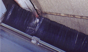
Wheel with Brush Seals
Seals: The seals act as the separation between the opposing airstreams. Properly designed they will prevent leakage around the rotor. There are two types of seals, contact and non-contact. Contact type seals are typically made of a soft neoprene or as a brush configuration. Contact brush seals have one disadvantage. As static pressure across the wheel increases the seals allow more leakage by the wheel. Brush seals should only be used in areas where the leakage is not a concern. Neoprene contact seals tend to wear out causing increased bypass and another maintenance issue. Non-contact seals are typically hard rubber and can be as simple as a rubber wiper set as close to the rotor as possible. Some manufacturers use a labyrinth type seal which uses the differential air pressure to create
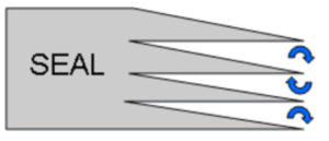 vortices that impede airflow past the seal. This type of seal can be very effective if the wheel is flat and the rotor does not deflect. One advantage of this type of seal is that as the static pressure across the wheel increases the labyrinth becomes more effective. Whatever type of non-contact seal is used, the important issue is that the seal does not contact the media. The media face can easily be damaged by abrasion with the seal.
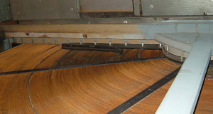
Wheel with Labyrinth Seals Held in Place by Clips
The key here is twofold. One, the seal must be firmly connected to the casing. Two, the wheel itself must not move. This will be covered later in a discussion of bearing and hub design. On the right is a typical non-contact seal held in place by clips. Although clips can assist in seal adjustment the seal can also be pulled between the media and the frame causing severe damage to the media face.
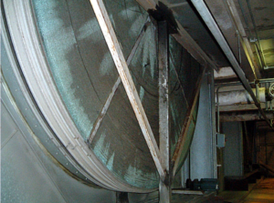
Wheel with Media Damage Caused by Bearing Failure
Hubs and Bearings: The hub and bearing assembly are crucial to the operation of the heat wheel. Forces of the wheel in operation are transferred through the hub to the bearings. Failure of either component will lead to severe damage to the wheel. In the picture to the right, a bearing set screw failed to allow the entire rotor to shift laterally in the casing.
The media was abraded by contact with the seals. The larger question is, “Why did the setscrew fail?” This design utilizes a shaft of “off the shelf” round
stock. The round stock has a +0/- 0.004” tolerance. Bearing specifications call for a + 0.0, – 0.001 tolerance. Over time undersized stock allows for movement of the shaft in the bearing race. This leads to setscrew and/or bearing failure.
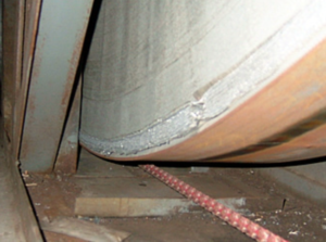
Wheel with Media Damage Caused by Bearing Failure
In the picture to the left. The entire rotor has skewed laterally. This caused major abrasion of both the seal and the rotor to the point that there is a 1/4” gouge in the media of the circumference of the rotor. The seal was abraded down to the sheet metal and the entire rotor continued operation to the point that the sheet metal was holding the rotor in place. This was caused by a bearing failure.
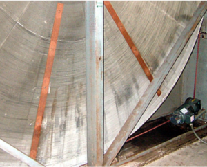
Wheel with Media Damage Caused by Bearing Failure
Here is the opposite side of the same wheel (on right). Note that there is substantial media damage. The bearing degraded such that the entire rotor could skew laterally over 1”. As the force of the airflow pushed the rotor into the seals it was being abraded on both sides.
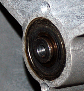
Wheel with Permanently Lubricated Bearing in the Return Airstream
Bearings and Shafts: The bearings are a key part of any mechanical system. There are two basic types – bearings that can be lubricated and “Lifetime Lubricated Bearings” which cannot be lubricated. Bearings that cannot be lubricated are sealed at the factory and can fail due to normal wear and tear or environmental factors. In this case, a four-year-old air handler with an energy recovery wheel had a failure of the bearing in the outside airstream. This unit was located in central Florida where humidity and temperature can place extreme loads on the bearing seals. Notice that in the same time period the bearing in the return air was in considerably better condition. Permanently lubricated bearings have the advantage of requiring no maintenance. The drawback is that rather than adding grease routinely, the only solution is bearing replacement.
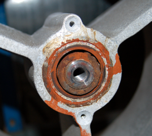
Wheel with Permanently Lubricated Bearing in the Outside Airstream
There are two types of lubricated bearings used in heat wheels, ball bearings, and tapered roller bearings. Most manufacturers provide ball bearings and, if sized properly and maintained, are a reasonable solution. On the other hand, tapered roller bearings of the same size can provide for a life span 10 times that of a simple ball bearing. Which ever bearing is selected one of the most critical areas that are often overlooked is the shaft that rides in the bearing. Most manufacturers provide a shaft that is “off the shelf” round stock. The diameter can vary by up to +/- 0.004”. Bearing manufacturers suggest +0.0, -0.001 for proper life. If the shaft is undersized there is a high probability of premature bearing failure.
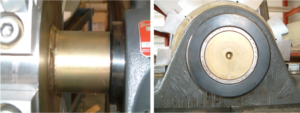
Thermotech Enterprises TF-Series Unit Tapered Roller Bearings
Motors and Drives: Although drive failures do not typically lead to severe wheel damage they can be an ongoing source of maintenance issues. Heat wheel manufacturers have tried several different combinations of pulleys, gears, chains, and belts to create a reliable drive system. The goal is basic. Design the drive system such that the motor can overcome the resistance of the wheel throughout its entire operating range while keeping the motor and associated parts as simple and reliable as possible.
Polyurethane belt: This type of belt has the advantage of being both elastic and flexible keeping constant tension on the drive sheave and rotor. The disadvantage is that after some time, typically 3-5 years, the material loses its flexibility and becomes brittle. These belts are welded together using a heat source similar to a soldering gun. The belts tend to fail at this joint unless the weld is expertly done.
Polyurethane interlocked link belts: This type has a better life than the solid polyurethane belt but does not provide elasticity so the belt must be tensioned by an idler wheel or in some other fashion. Chain Drive: This type although expensive is reliable. The drawbacks are that they require lubrication and are difficult to repair and replace. Standard V-belt drive. The standard V-belt has the advantage of superior life, it is easily found at most supply stores and is easy to repair or replace. This belt is not elastic so some type of tensioner is required. One manufacturer uses a uniquely simple system of gravity tensioned dual V-belts. The motor is secured to a simple pivot plate so the weight of the motor tensions the belt. This system is extremely reliable and requires no maintenance. Motors: The motor should be sized properly for the load and constructed to operate for 10 years minimum at maximum load. The motor will require some form of speed reduction to turn the wheel at the required RPM. This is accomplished by the use of reduction sheaves and belts. This adds to potential failures and increases maintenance needs.
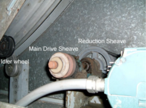
Drive with Reduction by Jackshaft Sheave
The picture to the left shows one manufacturer’s drive system. The motor turns a reduction sheave via a standard V-belt. The reduction sheave is connected via a jackshaft with two bearings that transfer the power to the main drive single V-belt via a spring-loaded idler pulley. There are a number of failure-prone areas and maintenance issues associated with this complex layout.
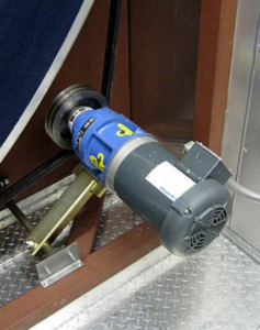
Thermotech Drive with Geared Speed Reducer
The picture to the right shows a Thermotech drive. This drive uses a gravity tensioned standard V-belt and a simple grease-lubricated geared speed reducer. This design greatly reduces the failure areas and requires no maintenance.
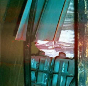
Single Piece Steel Rim Failure
Rims: The rim provides the structure to hold the rotor together and compress the media, eliminating movement within the spoke system. Higher compression of the media reduces media movement. The picture on the left shows a single-piece steel rim broke at the joint with the spoke. Constant flexing of the connection at the rim bolt connection caused metal fatigue which eventually caused a catastrophic failure.
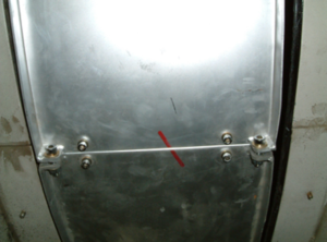
Note the size of the screws that join the rim sections.
The picture on the right shows one manufacturer utilizes a welded two-piece rim of a unique patented design that allows for individual compression of each media section. This can provide for a 10X increase in media compression. This eliminates media movement and the two-piece rim design provides enhanced strength eliminating metal fatigue that caused the single-piece rim above to fail.
Design Life: A reasonable expectation is an AHU component would last as long as an AHU – 25 years. The design life of the wheel is determined by the design life of the crucial rotor components. These are the components that are not easily repaired or replaced. These include the media, hub, shaft, and bearings. The easily replaceable components are the belts, drive, and motor. A good starting point for the lifespan is bearing life. A properly selected tapered roller bearing has been sized for a minimum L-10 lifespan of 290,000 hours or 25 years. It would then seem a reasonable goal to design all other critical components to this same standard. Thermowheel® bearings are designed for an L-10 life of 1,000,000 hours so that if poorly maintained they still meet our goal.
Reliability Summary:
There are 10 key reliability areas to take into account when selecting a heat recovery wheel.
• Segmented Media
• Low to Zero Deflection Spokes
• High Strength Rims
• Patented rim connection system eliminates media failures
• Tapered Roller Bearings L-10 life 1,000,000 hours
• Shafts Machined To Specified Tolerance
• Simplified Standard V-belt Drive
• Non-contact Low Bypass Seals Bolted To The Frame
• 10 Year Warranty On All Parts And Labor
There is one company that provides all these features and improvements in their heat wheel
products.
Thermotech Enterprises – Zero Failures Since 1985


